Tuesday, December 06, 2005

CerMark Laser Marks Survive The Rigors of Outer Space!!!

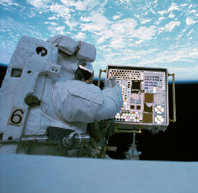
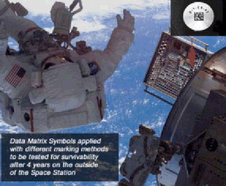
Ferro Corp.'s CerMark laser marking materials have survived nearly four years of Low Earth Orbit exposure on the exterior of the International Space Station. CerMark supplied bar code test marks on aluminum and glass, passing NASA's criteria for its Material International Space Station Experiment (MISSE). MISSE was a multi-stage experiment designed to establish part identification methods and techniques that might survive the rigors of space.

On the lower portion of the ISS airlock chamber, the marks were exposed to the experiment's harshest conditions, receiving the maximum amount of UV radiation and atomic oxidation. Post-flight, NASA evaluated each mark based on percentage of contrast, axial uniformity, print growth and error correction. The marks passed all of NASA's test criteria, grading no lower than a "B" on all of the markings.

"This is a significant achievement for CerMark's laser marking business and Ferro Corporation as well," said David Smith, sales manager, Laser Marking. "Our products have consistently produced high-quality, durable marks for years -- and few products can claim space as a test market. We welcomed the opportunity and are extremely pleased with the results."

For more information about CerMark's laser marking materials or the MISSE experiment, please contact Dave Smith at (800) 245-4951, ext. 5503, or at smithde@ferro.com

Monday, November 14, 2005

LMM-6000 Aerosol Cans Ready To Go.....

The new CerMark LMM-6000 Laser Marking Spray cans are now available again. This new package has been reformulated to prevent clogging and spitting issues you may have experienced before when using the aerosol cans. The new cans won't clog or spit, and spray performance has been improved. A new nozzle and propellant combination will provide a better spray pattern with more efficiency than the old can. The material's performance is unchanged. You will still get the same dark, black, high contrast mark as you achieved before with the old cans, or even with the LMM-6000 paste. All of the active ingredients are still the same, so you can now make the same high quality marks you need with an easier to use package.

To order a new can, please call Wanda at
(800) 245-4951, ext. 5167

Wednesday, September 21, 2005

Lining Up Marks - Part Two

Another technique we've found useful when lining up artwork or marks on an object is the use of black paper. Black paper is actually pretty hard to find in a store, so we make our own with a photocopier. If you run off some copies with the cover of the copier open and nothing in it, the copies will come out black. You can then use small pieces of this paper to test out the size of your markings. If you run the laser at a low power and a fast write speed, this will etch off the black ink and leave your image on the paper in white. You may have to experiment a little to get the settings just right. This can be a pretty handy tool for testing whether or not a particular design or mark will fit into a certain space on an object.

Monday, August 15, 2005

Finding the Right Power Setting

Working in the laser industry, I often field questions about proper power and speed settings. These questions are often difficult to answer as there are numerous variables that must be considered when seeking the proper settings. The type of substrate, thickness of the substrate, and laser wattage all factor into what settings will properly mark the material. For instance, aluminum conducts energy much better than steel, a thicker substrate will remove energy much faster than a thinner one, and a higher power laser can deliver more energy than a lower power laser. So what is the magic equation that crunches these variables into a perfect power and speed setting?

Well, in short, there is no equation that can calculate the perfect setting. But, there is a method which will allow you to quickly and efficiently determine a proper power and speed setting for any type of substrate you choose to mark. The key is to make a power/speed grid.

First, obtain a piece of your substrate, spray it with your marking material and focus it in your laser. (A scrap piece of the substrate is best, if possible, because you will ruin it making the grid).

Next, design a varying power/speed grid. For example, on stainless steel:

Steel 100P/50S
Steel 100P/40S
Steel 100P/30S
Steel 100P/20S
Steel 100P/10S

In this grid, P stands for % Power and S stands for % Speed. Adjust your lasers settings to match your selected colors and mark the substrate.

After you have marked the object, you should observe a variation of marks. They should range from barely visible to a slight destruction of the substrate. Pick a pair of settings that give a durable mark of the appropriate color that also maximizes your lasing speed.

Using this method first, when marking a substrate for the first time, can save you time and money. You are sure to only waste one piece of your substrate while quickly finding the optimum settings for the marking you need to do.

If you are using a lower power laser, i.e. 25 or 30 watts, and having trouble marking certain substrates, here is another tip. You can increase your Dots Per Inch (DPI) and deliver more energy to the surface of the substrate. Most lasers have a default setting of 500 DPI, but can be increased to 1000 DPI.

-LaserStud

Thursday, August 11, 2005

CerMark Laser Marks Return From Space!

DPM Data Matrix Samples Retrieved from ISS

The following is condensed from the August 2005 UID Newsletter, published monthly by Acuity CiMatrix. This article was written by Don Roxby of the RVSI Symbology Research Center, Huntsville AL.

Prior to the Space Shuttle Program, space-borne vehicles were expended; consequently their part identifiers were applied using marking processes designed for use in ground operations. With the advent of reusable space transportation vehicles and satellites, NASA needed to rethink how part identification markings were applied. Markings applied to reusable spacecraft need to survive the extreme enviroments encountered in space.

To support this new requirement, NASA approached RVSI to assist with a marking program to certify marking(s) for use in Low Earth Orbit (LEO). An experiment was designed to identify part identification methods and techniques that will survive the rigors of space. The experiment was to be designed to expose human and machine-readable markings to LEO environments. These include, but are not limited to, vacuum, solar UV radiation, micrometeoroids and space debris, atomic oxygen (AO) and deep thermal cycles. Working with the Boeing Phantom Works, RVSI Acuity CiMatrix’s Symbology Research Center applied markings to test coupons made of materials commonly utilized in the construction of the external components used on space transportation vehicles, satellites and space stations.

The test coupons consisted of 26 one-inch diameter disks, a 1-1/2-inch by 6-inch bar and a 4-inch square beta cloth blanket with fastener holes. The coupons were marked with labels, stenciled (additive) markings and direct markings applied using a wide range of different methods and techniques. (Note: CerMark's laser marking materials were a part of this test series) The material test coupons were then affixed to spaces provided on test panels, which were attached to the International Space Station (ISS) during a space walk conducted during the STS-105 Mission flown on August 10, 2001. The panels were positioned on the ISS so that they to could expect to receive the maximum amount of impact damage and exposure to a high degree of AO and UV radiation.

The experiments were recovered early during the STS-114 mission by Astronaut Stephen Robinson on July 30, 2005 when an opportunity presented itself during his record breaking six hours, fifty minute space walk. They were returned to earth on August 9, 2005. The marked coupons will be taken RVSI Acuity CiMatrix's Symbology Research Center where they will undergo a series of decoding tests designed to qualify identification processes for future retrievable spacecraft and satellites. Data from this in-orbit experiment will be added to NASA and military part marking standards.

For more information, contact Don Roxby droxby@rvsi.net , or visit www.uidsupport.com/newsletter/august_news/in_this_issue0508.htm

Thursday, August 04, 2005

What is Unique Identification (UID)?

The following is condensed from the UID support webpage, www.uidsupport.com, which is maintained by the RVSI Symbology Research Center.

Laser bonding and marking are MIL spec methods for meeting the requirements of UID.

UID is a new globally unique "part identifier" containing data elements used to track DoD parts through their life cycle.

UID Data is encoded into Data Matrix symbols that are applied to parts using Direct Part Marking processes (DPM). The DoD has moved to this transformation technology to facilitate electronic data capture and transmission.


UID is a mandatory DoD requirement for all solicitations issued on or after Jan. 1, 2004. The DoD Download --- The DoD Guide to UID - Version 1.5 requires the application of Data Matrix symbols to parts in the following categories:

• Costs over $5,000.
• Serially managed.
• Mission essential.
• Controlled inventory.
• A consumable item or material where permanent identification is necessary.

For more information, visit http://www.uidsupport.com/

Tuesday, August 02, 2005

Lining up a mark on an object

When marking with CerMark LMM-6000 or 6038, we use a useful technique here in the lab to help us line up our marks. To test the position of the mark, the LMM can first be discolored using very low power without bonding it to the metal. For example, if using a 35 watt laser, you can run the mark at about 10% power and 100% speed to see its position. The LMM will be discolored on the surface, but it won't be bonded to the metal. If the positioning is correct, you can then mark normally at 100% power and your usual marking speed. This can be very helpful in lining up an image on an odd shaped part.

Note: Be careful not to use too much power when trying this, if you bond any LMM to the part it will be very difficult to remove it without ruining the piece. It is better to start off too low in power than too high.

Sean